This circuit was originally designed to detect weak flashed of laser light bounced off of a fabric video projection screen. It was used as part of a firearm training system. It generates a 100mS output pulse whenever it detects a 3ms to 5ms-laser burst, modulated at 40KHz. It is very sensitive and could be modified for long-range laser communications.
Monday, November 15, 2010
Fake Car Alarm Light
Whenever the car’s ignition is turned off, this circuit activates a flashing LED, which can be positioned to appear as an active alarm system.
1.5V LED FLASHER VERSION A
Judging from the numerous references I have received, this electronic circuit, hobby circuit seems to be rather popular. Many published circuits which flash LEDs need 3 or more volts. This electronic circuit uses only a single inexpensive C-MOS IC and flashes the LED for a full year on a single 1.5 volt AA alkaline battery cell. The circuit uses a charge pump technique to provide the LED with the needed voltage. This electronic schematic will only work on red, green and yellow LEDs. It is not be able to flash white LEDs.
Cell Phone Helper
When your cellular phone receives a call, it begins transmitting even before you answer. The circuit shown in fig.1 detects this signal and can operate a variety of devices referred to as "load".
Demodulator
The demodulator block diagram below has three major sections that were implemented in this iteration of the design:
1) The Mixer,
2) The Filter,
3) The Phase Shift Network
Experimental 1 KHz Synchronous Detector
OverviewThis circuit employs a synchronous demodulator to separate a 1 KHz signal from noise and measures the amplitude of the 1 kHz signals once a second at about 60 microvolts per count then sends the measurements via an RS-232 interface for further processing or display. An LED on the board also lights when the measured signal exceeds a preset threshold.
Operational Amplifier (Op-Amp) Basics
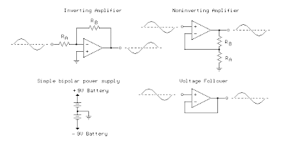
The op-amp is basically a differential amplifier having a large voltage gain, very high input impedance and low output impedance. The op-amp has a "inverting" or (-) input and "noninverting" or (+) input and a single output. The op-amp is usually powered by a dual polarity power supply in the range of +/- 5 volts to +/- 15 volts. A simple dual polarity power supply is shown in the figure below which can be assembled with two 9 volt batteries.
Subscribe to:
Comments (Atom)


